About the Wiki
Team 1516B is a Vex V5 Robotics Competition team based out of San Ramon, California. In this wiki, we try to explain the workings of our robot and how they were implemented from a high level perspective. This wiki resembles the extremely well made BLRS Wiki.
However, Purdue SIGbots designed their wiki as a knowledge base for information about robotics and about the VEX ecosystem, while this wiki tries to take a more example driven approach by focusing on describing our robot, and our specific insights and findings.
The robot
This chapter goes over the specifications of the 1516B robot and will continually update to reflect the latest version of the robot first. Previous iterations of the robot for this season will be pushed down as necessary in order to place the specifications in reverse chronological order.
Drivetrain
Semester 1
Currently, Team 1516B uses a 6 motor drivetrain with omniwheels for fast movement, and also uses gear ratios optimized for speed on the drivetrain. We aim for a fast drivetrain that can move the robot around and push triballs as well as one that has enough torque to overcome an opposing robot pushing ours backwards.
We put 4 motors in the back in order to save space in the middle for a triball holding area. As we have defined the game, Over Under, this year as a "pushing game", our intake serves moderately little use except as a holder for our beginning autonomous. Therefore, our drivetrain must be one of the strongest portions of our robot.
Semester 2
During the second half of our season, we rebuilt the drivetrain, using the same six motor drivetrain idea, but instead using 8 wheels for the drivetrain and making the motors equidistant from one another. Additionally, we built a drivetrain for the programmers to test code on, which was also a six motor drivetrain, but it had six larger 4 inch wheels. The 8 wheels on the main drivetrain were to allow the bot to get over the center bar easier and have more stability in general.
Wings
Additionally, we use two pneumatics that power horizontally locking wings on each side of the robot. They are controlled together and have polycarbonate plastic on them to push triballs forwards easier.
PTO System
The PTO sytem, or a power takeoff system, is essentially a mechanic that transfers power from a motor to different systems as needed. In our case, we control the movement of power from the motors using gears and pneumetics. We developed this system during the second semester of the Over Under season.
The PTO system is powered by two motors, connected to a gearshaft at the bottom with a sliding gear controlled by a double action pneumatic, that is positioned horizontally to push a gear into place. to determine whether the gear is powered or not. Depending on the state of the first pneumatic, power is either transferred to the intake or to the lift/shooting mechanism.
The second double action pneumatic right above the first one controls whether the power input goes to the 4 bar(lift) or the flywheel(shooting), by connecting a gear to a gearshaft if active or retracted. The gearshaft connected then transfers the power to the subsystem using it. Using these two, we have 4 possible configurations to transfer power to subsystems. Since only 3 subsystems need power from the PTO system, the 4th potential case is left unnacounted for in the codebase.
Intake
Semester 1
The original intake for the first semester of the Over Under 23-24 season was made with a large chain gear and rubber bands between the two side gears in order to grab onto the triball and intake it. During competitions, the intake's rubber bands seemed too thin to move the triballs in and out of a holding area right behind the intake. It was slow and the rubber bands bent more than was efficient.
Semester 2
For the second semester of our season, we decided to rework the intake of the robot and use flex wheels instead of rubber bands to pull in the triballs. We designed it such that around 6 flex wheels would be parallel to the rotation of the chain gear and would roll inwards the same direction as the triball would move inwards to the holding area. The flex wheels provided a more firm grip on the triball, making it easier to hold the triballs and push them out when necessary. Additionally, since the wheels were rotating the same direction as the chain gear that powered it, more force from the motors were transferred to the flex wheels' rotation rather than with the rubber bands, where the force applied was perpendicular to the orientation of the rubber bands. Additionally, the flex wheel intake was more reliable for us in our autonomous routine test than the rubber band intake was.
The second semester intake is powered by the PTO system, which transfers power from two motors in the back to the chain gear connected to the flex wheels through pneumatics that connect two gears together, transferring power through chain rotation to the gears that power the intake.
Shooting
Semster 1
For the first semester of the 23-24 Over Under VEX season, we used a catapult to throw triballs over the center bar, used in both skills and match loading for the robot. The catapult was made with a slip gear and a ratchet to make sure that it did not move backwards. When the slip gear was hit by the gear controlling the actual catapult, rubber bands pulling the catapult towards the gear took control, and shot the catapult forwards with the triball, throwing the triball over the center barrier about 50% of the time.
The issues with this design were that the number of rubber bands put excessive stress onto the bars that were holding the catapult and gear on place, and eventually caused enough wear and tear on the gears that were running that catapult that it would be better to replace it. Additionally, during mtch loading and skills, the design of the catapult made it so that it was very easy to drop the triball into the holding area, forcing double possession if holding another triball for us.
Semester 2
We decided to replace the catapult with a flywheel design for the second semester of our Over Under season. On our PTO system, we have a pneumatic setting that redirects power to a gear with another chain gear on the same shaft. The chain gear transfers power through chain to a shaft on the lift, where other gears transfer the power over to the flywheel, using a gear ratio of large to small in order to optimize for the fastest speed possible, shooting as far from the loading location. This design solves the issue of thee tribaaalls dropping into the loading zone and getting stuck, forcing double posession. On the flip side though, the flywheel takes a lot of torque to run and so has a much slower startup time and greater energy consumption that the catapult.
Lift
Semester 1
We did not use a lift for the majority of the first semster, but did use a blocker which was activated by a piston
Semester 2
In our second semester, we decided to combine both our system to shoot match loads over blockers from other teams as well as to block other teams. We decided to complete this task by building a 4-bar lift that would help us gain the height to complete both of these functions relatively easily. To see the principle of how a 4 bar is built and works, see the link given beforehand. In general, a 4-bar lift looks like the following, with the further end buing pulled upwards.

Our four bar houses the PTO system in the rear side as well as the power transfer mechanisms for the lift/shooter and the intake. The middle contains the power transfer gears to run the shooter and the very end of the four-bar contains the flywheel itself. The 4-bar lift is also powered by a certain pneumatic setting to redirect power from the PTO to the 4-bar, that will help lift and bring down the 4-bar. It uses a ratchet to keep the 4-bar up when shooting/blocking, to keep it from falling back down.
Resources
This page contains assorted external resources for the vex ecosystem.
BLRS Wiki - This is the BLRS wiki. It contains a lot of information on engineering, building, and many other things, and comes from the creator of PROS, Purdue SIGBots. Here is a relevant Vex Forum link.
Additionally, some other knowledge wiki-like information that was found are:
- 7842F Explanation - This is an explanation of the strategies used by a team to gain success. They have an advanced codebase, and it would be beneficial to learn from their experiences.
Code Specific:
Programming
This section describes the code used for the robot and the different programs and structures used in each of the iterations/versions of our codebase.
VEXCode
Codebase
This page goes over the original code written for the 1516B Over Under Season in 2023, where the code was made using the VEXCode framework and was in use primarily during the months of June to December.
Portions of the program
The portions of the code contain a user control function and a autonomous function, which further contains the rerun function. The rerun function also contains helper functions that are called from both the autonomous and user control functions. So, a visualization of the functions made in the program would be as follows:
Helper Functions(Rerun)
User control
- Rerun write call
- Rerun execution time recording
Autonomous control
- Rerun reader call
- Execution and replay of recorder motor values
- Inclusion of sensor values into the calculation of rerun
Rerun - Autonomous
Essentially, the rerun function records the velocities of the motor encoders as well as the time taken per each execution loop in the user control program. This value is required because the loop execution time is necessary to update the different motor velocities in the autonomous function as they need to be called.
The recorded values are put into a text file. These values of the motor velocities are replayed by simulating a user control loop(in our case, a while loop checking for controller events) and adding a wait time for simulating latency in the user control loop. This wait time has been recorded along with the motor velocities and is accurate to a microsecond level.
The motor encoder values are read and the robot perceives the autonomous program similar to how it would see the control loop, except with predefined instructions.
User Control
The 1516B user control function uses relatively simple and straightforward checks of controller events inside a controller loop. It also uses a tank drive approach.
The rerun function recording is called from inside this user controller function, where the latency of the user control loop and motor encoder values are recorded into their appropriate text files.
Helper Functions
The helper functions for this program are for a variety of tasks, some being serializing data to fit into a certain data type limited by the framework we are using, as well as actually writing to and reading from files to receive usable data for the rerun or another portion of the code.
PROS
Codebase
Over the break between semester 1 and 2, we decided to migrate our codebase from VexCode into PROS. We did this as we believed that PROS could offer us greater control and innovation opportunities than that of VexCode. As we migrated the codebase, we decided to change some functions in our program from the VexCode version, to suit the newly rebuilt robot made for the second semester of the Over Under season 23-24.
User Control.
For user control, we implemented a tank drive system that would use one joystick to control each side of the drivetrain. It allows for the driver to get better control of each side of the robot and lets the driver perform error correction if a motor somehow fails in the middle of a match.
int left = controller.get_analog(pros::E_CONTROLLER_ANALOG_LEFT_Y);
int right = controller.get_analog(pros::E_CONTROLLER_ANALOG_RIGHT_Y);

// std::abs takes the absolute value of whatever it is called on.
// Thus, any values in range (-5,5) are discarded as 0.
if(std::abs(left) < deadzone) {
    left = 0;
}
if(std::abs(right) < deadzone) {
    right = 0;
}

// Drive the left side of the robot forward at joystick left Y speed
drive_left.move(left);
// Drive the right side of the robot forward at joystick right Y speed
drive_right.move(right);
Our motors are split into 3 groups, two being the right and left sides of the drivetrain respectively, and the final group being the two motors powering the PTO system. The pneumatics are controlled independently but are generally grouped into the PTO pneumatics and the wing pneumatics.
The PTO motors are controlled by basic controls that run the motor group on the PTO when the R1 or R2 button is pressed, to go forwards or backwards respectively. The wings are set with a toggle that turns the pneumatics on with a button click and then turns them off if pressed again.
Additionally, a toggler has been implemented that allows the driver to control the subsystem of the PTO with an easier user interface, by toggling through the PTO options. The toggler automatically adjusts the pneumatics to direct power to the subsystem labeled on the controller. The code used to implement this system is under:
if(controller.get_digital_new_press(pros::E_CONTROLLER_DIGITAL_X)) {
			if (subsystem == 1) {
				// intake
				controller.clear_line(0);
				pto_1.set_value(false);
				controller.print(1, 0, "System %d : Intake", system);
			}
			if (subsystem == 2) {
				// Four Bar
				controller.clear_line(0);
				pto_1.set_value(true);
				pto_2.set_value(true);
				controller.print(1, 0, "System %d : 4-bar", system);
			}
			if (subsystem == 3) {
				// Flywheel
				controller.clear_line(0);
				pto_1.set_value(true);
				pto_2.set_value(false);
				controller.print(1, 0, "System %d : Flywheel", system);
			}

			subsystem = subsystem + 1;

			// Checks if the toggler goes out of bounds.
			if (subsystem == 4) {
				subsystem = 1;
			}

		}
Autonomous control
For the autonomous period, we mainly focus on using our drivetrain to move the robot to the goal and place a triball in. We have not used our subsystems extensively in the autonomous period due to how unpredictable they could potentially be and how they could leave the robot in a state that is unwanted. Therefore, we are focusing on achieving simple goals and compounding them, such as delivering a triball to the alliance goal zone.
We have a inertial sensor, and use it in coordination with built-in motor encoders for odometry. We use an external framework to manage the mathematics and calculations of this function for us. We use the same framework to manage our pure pursuit path and by extension our autonomous routine. We use PID controllers to manage our speeds and ensure that the robot reaches its appropriate goal most of the time.
PROS Rewrite
Firstly, we began documenting our code using the autegnerator Doxygen. We did this so that future teams can learn from our code if they would like and it gives them an easier way of getting started: Doxygen documentation
This page documents the rewrite of the codebase completely in pros from a single main.cpp file, that adhered to the recommendations given by the PROS
documentation, to the full fledged codebase following OOP(Object Oriented Programming practices) and following general good C++ practices, rather than the code existing in a bubble
inside the VEX ecosystem.
At the core, most of the functionality of the robot remains the same from before the rewrite(commits before January 2024) in the codebase) Some of the main functionality that is different comes along with the rebuild of the robot, as is in the usage of the distance sensor for the puncher(Doxygen documentation->class list->puncher->toShoot() docs), as well as some differences between the codebases for global variable declarations(Doxygen documentation->namespace list->globals namespace).
One of the most influential additions to the codebase is the addition of the toggler, which allows to dynamically change the settings of the subsystems. This includes, but is not limited to the drivetrain drive mode, whether the puncher uses a distance sensor or not, and what the autonomous to run will be.
It is easiest to explain how the new codebase is structured with the autogenerated Doxygen documentation.
Otherwise, most of the logic is the same as previous, and the methods and functionality relating to different subsystems are just split up into their own interfaces in order to promote better code quality.
Initial Research/Analysis
- Consists of the top 100 skills teams. Note that multiple different abbreviations are used in this table without consistency. Use search engines to understand their definitions wherever necessary.
- These are our personal opinions and judgements about the following robots and means no harm or criticism by this research.
- Completed on 12/22/23
Please use the scroll bar at the bottom of the table to see more information towards the right
| Ranking | Team | Drivetrain | Intake | Blocker | Launcher | Wings | Elevation | Notes | Picture |
|---|---|---|---|---|---|---|---|---|---|
| 2 | 87867D | 8 m, 4whl drive, mecanum whls | N/A | Puncher | 2 bar with puncher | 2 piston vertical wings | Puncher elevation | Uses a PTO for puncher and blocker | 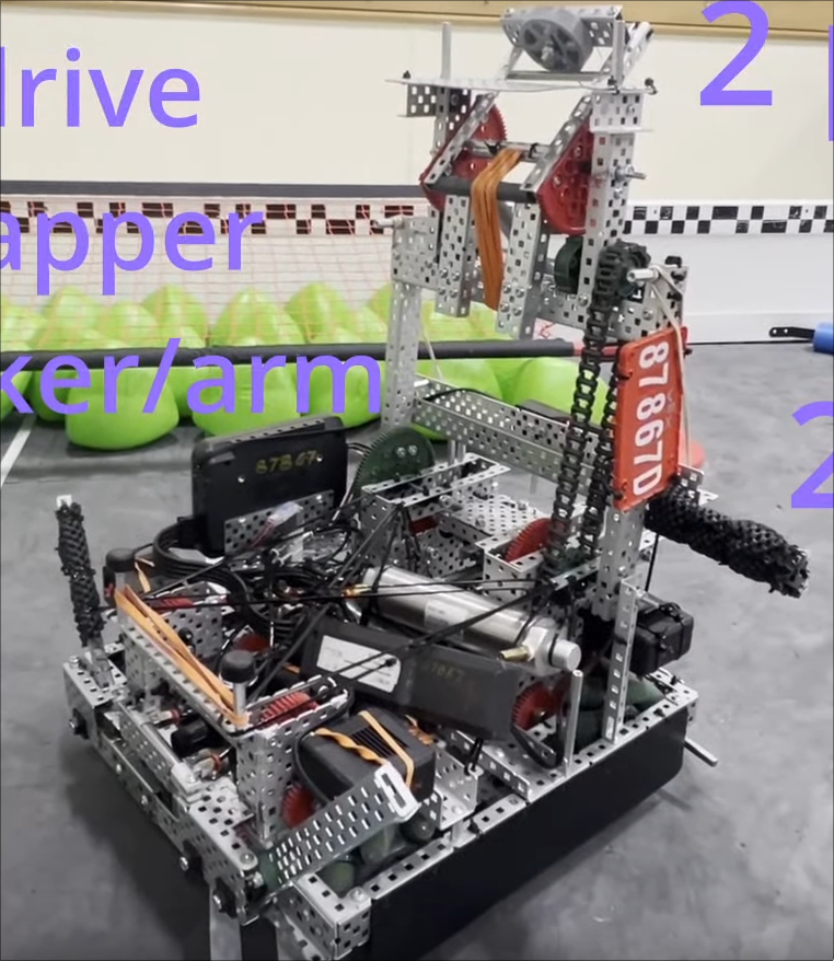 |
| 3 | 229V | 6m, 450rpm, 2.75in drive, 36:48 gear ratio | 1m 600rpm Sprocket rubber bands | 1 piston, 2 C-channels with poly | 1m 33rpm Catapult with standoff puncher | 2 piston horizontal wings | Passive elevation | Design seems a bit old | 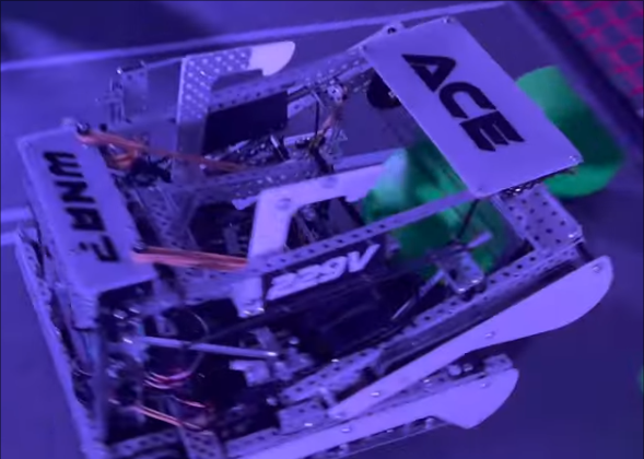 |
| 4 | 2029C | 6m, 450rpm, 2.75in drive | 1m 600rpm roller intake | Launch Blocker | 2m lift, 1m 40rpm double slip shooter | 2p horizontal wings | Passive Elevation | Uses 2p PTO and gears for 4 bar lift | 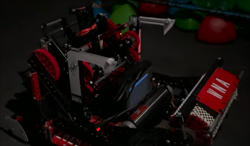 |
| 7 | 2654P | 6m, 450rpm, 2.75in drive, 4whl | 0.5m 400rpm roller intake | N/A | 1m 100 shots per minute puncher; uses horizontal standoff | 2 piston vertical wings | N/A | Incredibly consistent puncher! | 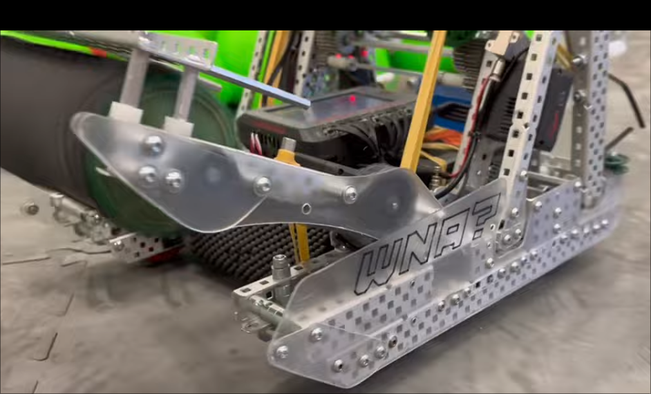 |
| 8 | 66475C | 300rpm, 4in whl, 6 whls | 1m, Sprocket rubber band intake | Folding L-channel with string, piston activated | Catapult with standoff puncher | 2 piston horizontal wings | N/A | Like our old bot but better | 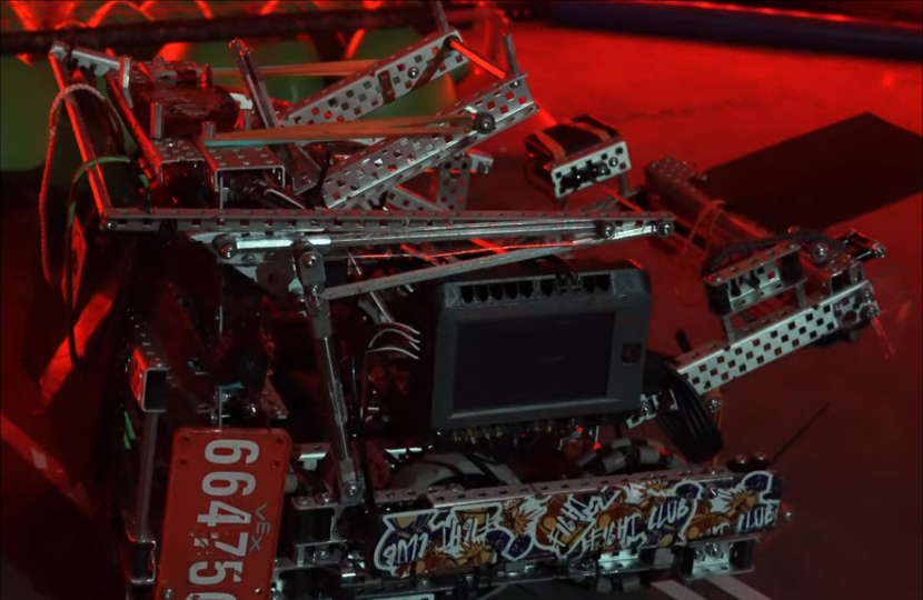 |
| 10 | 2775V | 6m, 3.25in whls, 360rpm? | 1m, Sprocket rubber band, Chain driven, motor in back | Launcher lift | 2 piston 4 bar lift, half l-channels, Puncher ratio unknown | 2 piston horizontal wings, not locking, bent polycarb | N/A | Really nice lift, odometry uses two tracking wheels | 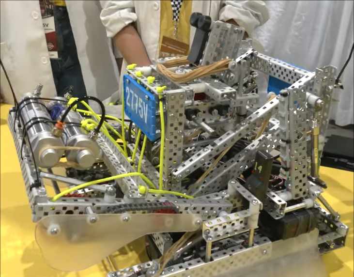 |
| 12 | 48425A | 6m, 360rpm drive, 3.25in whls | 1m, Dual sprockets rubber band | N/A | 1m Catapult | 2 piston horizontal wings, non-locking | Passive Catapult | This is our old robot! | 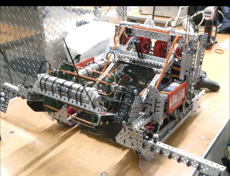 |
| 15 | 323V | 6m, 6 whl, 3.25in whls | 1m, Roller intake | N/A | 1m Catapult | 2 piston locking wings | Passive Catapult | Carbon Copy. Also pretty old | 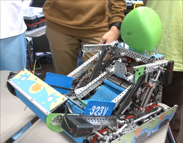 |
| 18 | 99904B | 6m, 6 whl, 3.25in whls | N/A | Passive String Blocker | 2m Puncher | 2 piston locking wings | 4 piston hang, B tier | Puncher is powered by PTO/Puncher between hang mech | 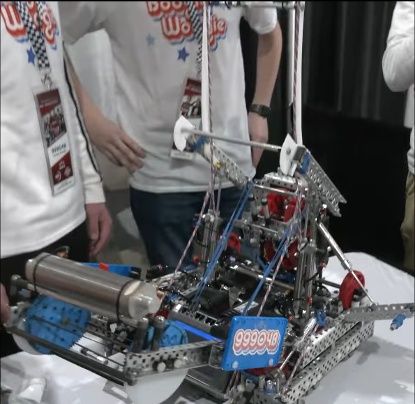 |
| 21 | 8889A | 6m, 300rpm, 6 whl, 4in whl | 2 0.5m flexwhl intake | 1 piston, 2 C-channel with poly | 1m Cata/Puncher | 2 piston wings | 4 piston hang, B tier | Seems like a solid bot | 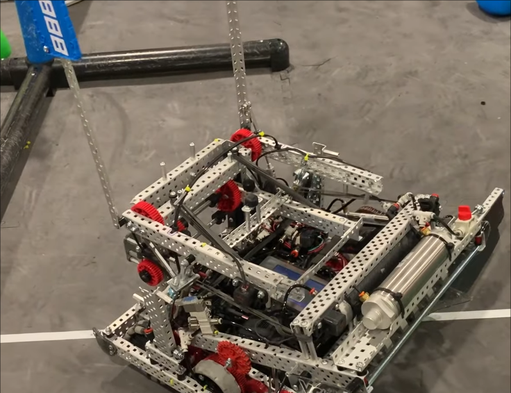 |
| 24 | 5203G | 6m, 360prm, 8whl, No Traction | 1m, Sprocket Rubber band intake | N/A | 1m Puncher | 2 horizontal wings/2 vertical wings | 4 piston hang mech | Battery and Air tank in drivetrain/Simplicity is key | 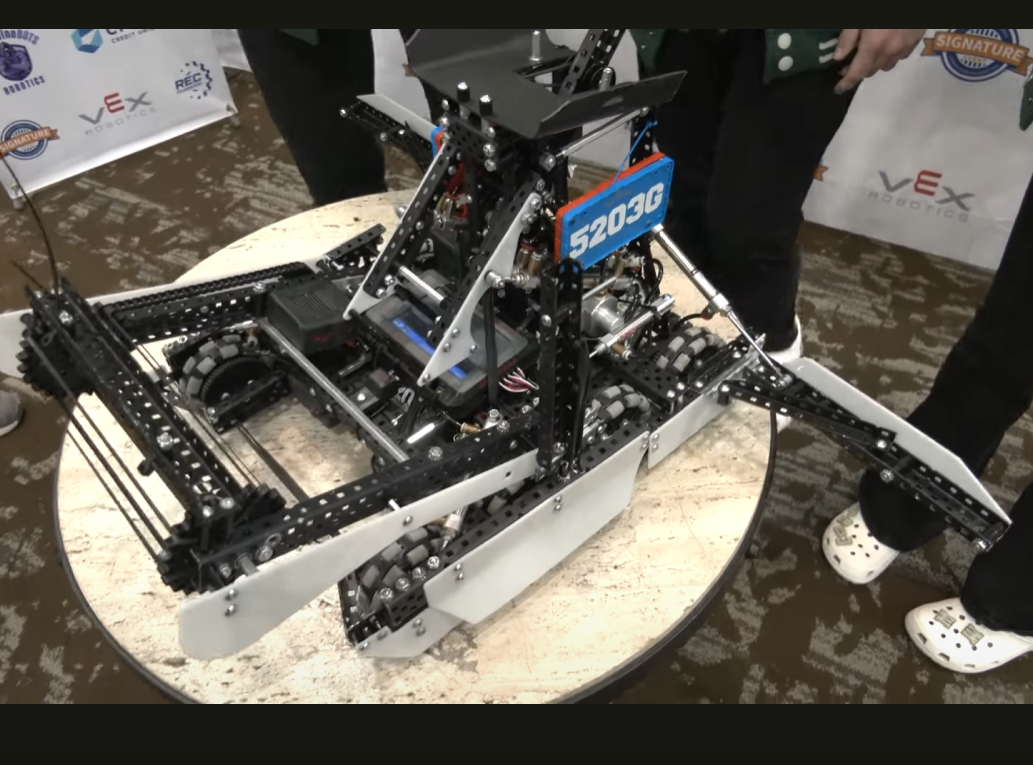 |
| 25 | 9364C | 4 + 2 0.5m, 400rpm, 6whl, No Traction, | 1m, Sprocket Rubber band intake | Launcher lift | 1m Puncher, 72:24 Gear Ratio, 33rpm | 2 horizontal wings | 1 motor lift with adjustable ratchet | Unique 55W drive and no PTOs unlike others with similar design. Also has offset 4 bar. | 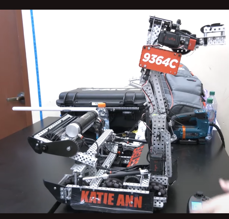 |
| 30 | 100A | 6m, 330rpm, 6whl, No traction | 1m, 600rpm, Small sprocket rubber bands/High strength | N/A | 1m, 60:12 gear ratio, 33rpm Catapult/Puncher | 2 horizontal locking wings | 2 piston hang mech | Carbon Copy. Uses a small sprocket for intake which is unique. | 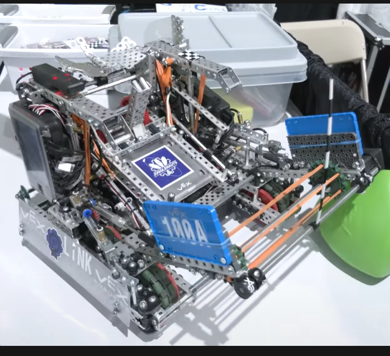 |
| 35 | 2011A | 6m, 343rpm, 6whl, 4in, raised center whl | 1m, Roller intake, 2 bar design | 4 piston blocker | 1m Cata/Puncher | 2 horizontal locking wings | 4 piston blocker/hang mech | Integrated blocker/hang mech | 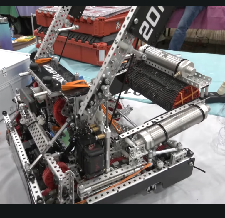 |
| 38 | 96504C | 6m, 72:36 gear ratio, 6whl, 4in omnis | 1m, Sprocket rubber band, 2 bar | N/A | 1.5m Puncher, 133 shots per minute, uses optical sensor | 2 horizontal wings | Long Barrier Balance | Use of optical sensor allows for maximum match load efficency | 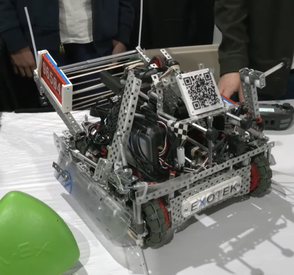 |
| 40 | 80508X | 8m, 450rpm, 8whl, 2.75in all omnis | 4m, Sprocket rubber band, 2 bar | 4 piston blocker with 2+2 configuration | 4m Cata/Puncher | 2 horizontal wings | Long Barrier Balance | 2nd bot to use 8m drive with PTO | 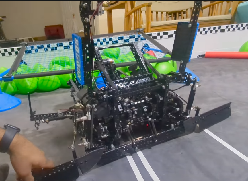 |
| 41 | 338A | 6m, 300rpm, all omnis, 4 4in whls, 2 3.25in whls | 1m, 600rpm 2in flex wheel intake, 2 bar | 2 piston blocker with string | 1m Puncher, 100rpm, 36:12 gear ratio, 12t with 6t shaved | 2 horizontal wings | A tier Long Barrier Balance | Taller blockers are really important | 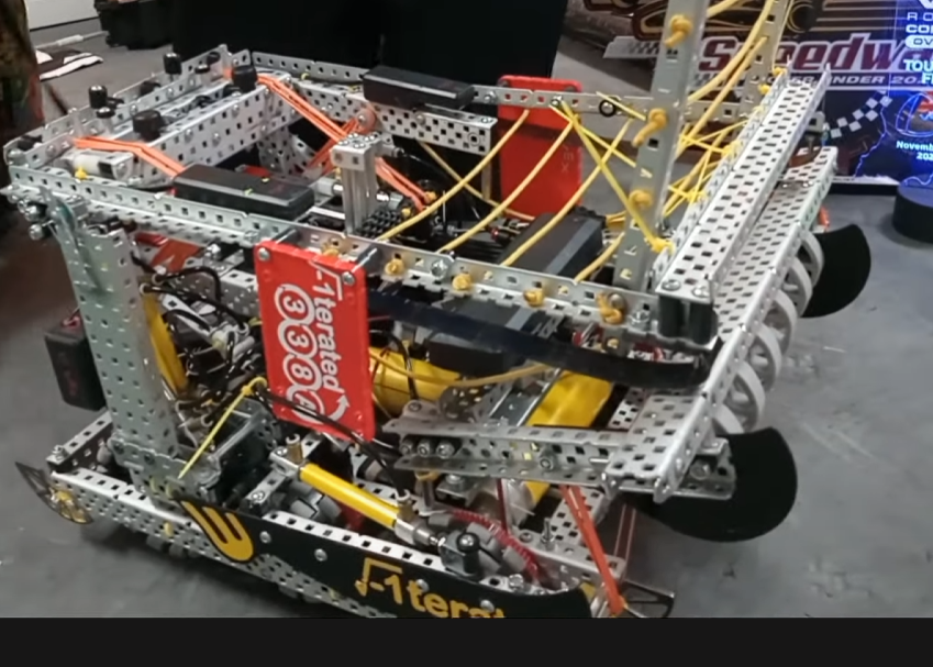 |
| 51 | 11101B | 6m, 360rpm, 8x3.25in omnis | 1m 2in Flex whls | 1 piston blocker | 1m Cata/Puncher | 2 horizontal locking wings | Long Barrier Balance | Carbon Copy. Traction wheels aren't that necessary. | 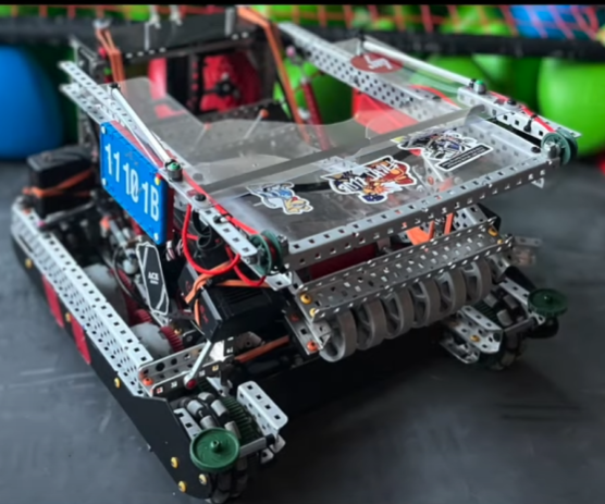 |
| 52 | 8926W | 6m, 360rpm, 8x3.25in omnis | 1m Dual Sprocket Rubberband 4bar | N/A | 1m Puncher | 2 horizontal wings | Long Barrier Balance | Really like the wing design, I think we could copy this aspect | 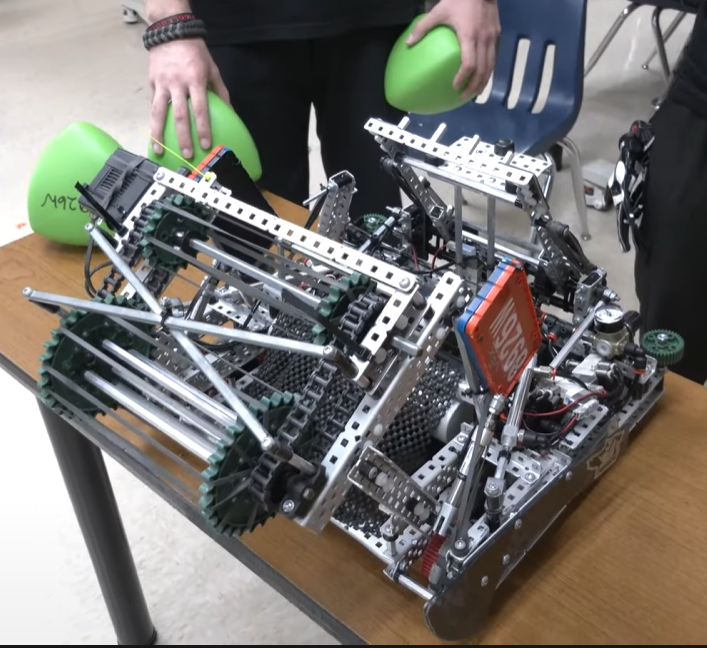 |
| 56 | 19589A | 6m, 8x3.25 omni | 1m, Sprocket Rubber band 2 bar | N/A | 1m 25rpm Puncher, 4 bar lift activated by 2 pistons | 2 horizontal wings | 4 bar lift | Uses a lot of pistons but good starting place. | 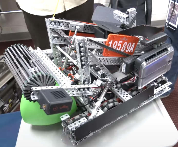 |
Internal Forces (Stresses)
All physical objects can experience stresses as a result of external forces being applied on it. This also applies to a robot built for the VEX Robotics Competition. Robots can experience many different types of stresses, but the most common are:
- Bending
- Shear
- Torsion
- Compression/Tension

MikeRun, CC BY-SA 4.0, via Wikimedia Commons
Bending
Bending is one of the most common types of stresses present in a VEX robot. It occurs when an object experiences a force perpendicular to its normal axis. Bending is very common in drivetrains, polycarbonate sheets, standoffs, and lifts.
Torsion
Torsion is a more specific type of stress. It can occur when an object experiences a force tangent to its normal axis. It is very common to see torsion present in low strength shafts, bars, and other types of long objects with very little support. High torque applications exert more torsion and require special types of gears and axles to avoid damaging parts.
Shear
Shearing is another very common stress. Shear stress occurs when an object experiences a force parallel to its cross section. Most robotics parts are able to withstand shear stress, but the connections that fix the part in place often cannot handle the torque. This can result in rotated or non-orthogonal structures. For example, a weak drivetrain without proper bracing when subjected to a shear force could form a rhombus shape that interferes with normal movement.
Compression/Tension
This is the least common stress in robotics. Compression or tension can occur when an object experiences a force parallel to its normal axis. This stress is mostly present in fasteners such as screws and nuts and keeps the robot together. Over time, these forces can lead to shaft collars separating from their axles. Compression and tension forces are also present in lifts.
Examples

In this image, can you spot each of the different forces that could act on potential mechanisms of this robot?
For the wing, shearing can occur and cause a torsional force on the outer drivetrain c-channel. Because the wing is also attached to the piston, a shearing force on the wing would cause a small tension force on the piston. In this case, the biggest issue would most likely be the torsional stress experienced by the drivetrain. This could cause additional friction on the axles, or even loosen the shaft collars.
The wheel guards are built with two angles and a line of connected standoffs. The standoffs could experience a bending force if they were hit in the middle. Additionally, this might cause a torsion force to be applied to the screws, which loosen them and cause the wheel guards to get caught in the omnidirectional wheel.
Finally, a bending force in the ramp could cause a tension force in the shaft collars, leading to a loose ramp. This could act as a wedge and prevent the robot from moving in the forwards or backwards direction.
These examples should make it clear how these different types of forces can act a robot and its mechanisms.
Real World Examples
Which part of the robot in this photo is the weakest when subjected to a shear force?
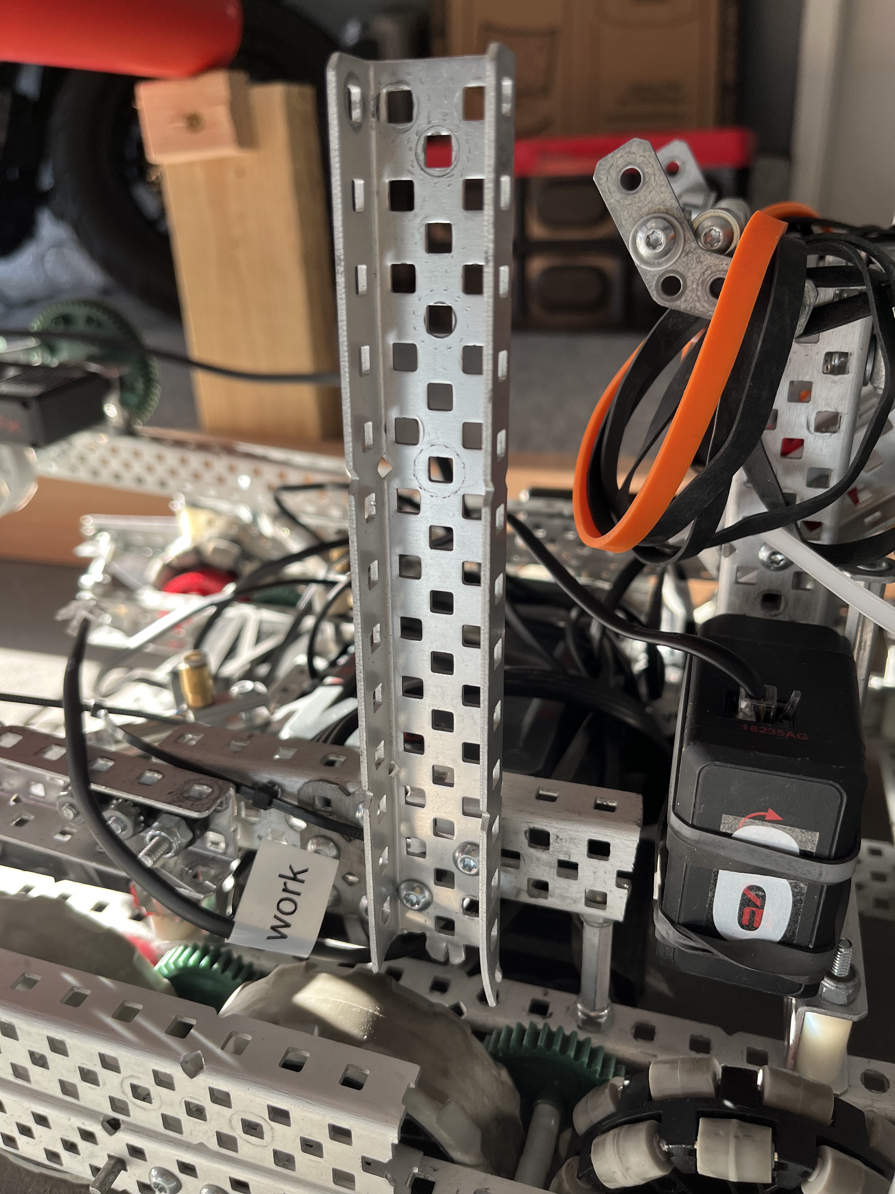
If it was unclear from the image, the correct answer would be the vertical c-channel. This c-channel is designed to support a horizontal bar passive hang from Over Under. The function of this mechanism requires the robot to drive forward into the bar. This causes a shear force to be applied to the c-channel. Without any additional support, the torque force will overcome the compression force of the screw. To mitigate this, diagonal supports should be added to support the c-channel such as angles or bars. These have a much larger compression/tension force and will keep the structure rigid.
Analyzing mechanical structures requires a critical thought process. Every single aspect of the mechanism must be considered in all possible scenarios to determine whether it will be structurally sound. A three step process can be used to determine whether a mechanism can withstand potential stresses:
- What functions does the structure have? Does it touch other parts of the robot?
- If the part does touch other parts of the robot, further analysis is required.
- What potential forces could be applied to the part? Does it have a range of motion? A simple test would be to operate the mechanism and see what moves; this would help determine where and how forces could be applied.
- Each potential force should be nullified by an equal and opposite stress force (usually compression or tension). If a potential force is not counteracted by a stress force, the mechanism structure should be revised.
Best Practices
- Triangle structures resist external forces much better than square structures.
- A good rule of thumb is to make sure each structural member (i.e. c-channels) is always attached to two other structural members at different vertices.
- High torque applications require high torsional stiffness, in other words, use high strength shafts instead of low strength, and angles instead of bars. Always use the stronger variant.
- Properly brace structures; form triangles in your subsystems when ever possible.
Contributions
This wiki is made, curated, and updated by the members of the 1516B VEX VRC Team. We aim to note down information about our robot and strategy that would prove useful to other people in the VEX ecosystem.
As of the Over Under 23-24 Season, the contributors to this wiki are Absozero and Centei.